| Order Code | CFEASL4 |
|---|---|
| System | Emergency Assist |
| Product Type | 4-Way Indicator |
Integration of an emergency disabled assist system
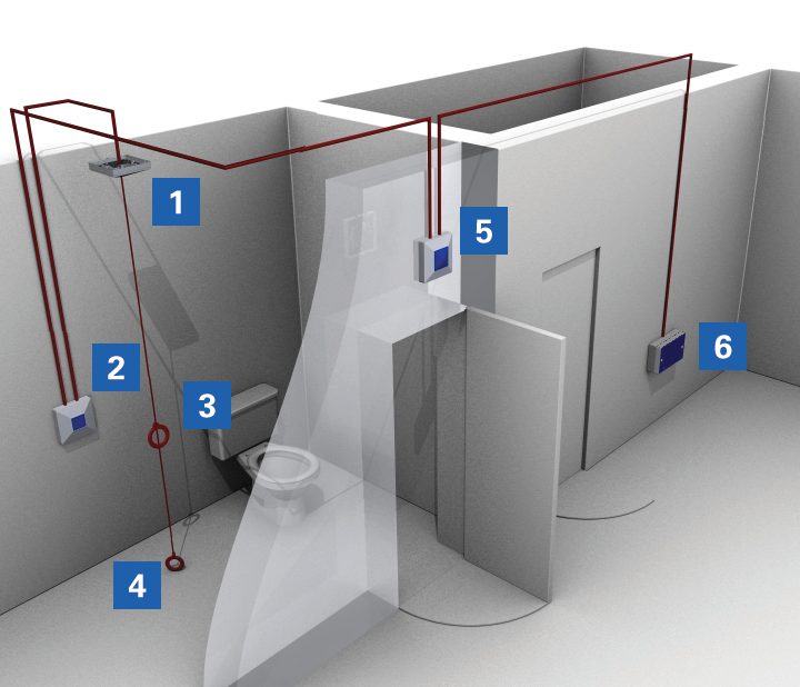
1. The Ceiling Pull should be positioned so that its readily accessible from the WC or bath (where applicable).
2. The cancel button should be positioned so that it is reachable from the WC and a wheelchair.
3. The upper cord pull should be located between 800mm & 1000mm above floor level.
4. The lower cord pull should be exactly 100mm above the floor level (remove excess cord).
5. The over door indicator provides an audible and visual signal to indicate the area where assistance is required.
6. The power supply is situated in the corridor and supplied via a switched fuse spur.